손은종 , 전재홍 , 박기성
탄소섬유 블레이딩 강체의 직조조건에 따른 강체의 물성변동에 대한 고찰
Investigation into the Variation of Physical Properties in Carbon Fiber Composites (CFRP) according to Braiding Conditions
Eun Jong Son, Jae Hong Jeon, Ki Sung Park
Abstract: This study investigated the braiding weaving method and the resulting tensile and flexural properties of rigid bodies based on different types of carbon fiber yarns. The research examined the physical properties of rigid bodies at various weaving angles using T700, T800, and PITCH-based yarns. The results revealed that the type of carbon fiber yarn directly influences the tensile characteristics of the rigid body. T800 yarn exhibited high strength, while PITCH-based yarn demonstrated high elongation, confirming that each yarn maintained its relative characteristics. The study found that the properties of braided rigid bodies vary depending on the yarn properties and weaving angle. At 0 degrees (UD direction), the rigid bodies displayed pure carbon fiber characteristics. However, as the weaving angle increased, a transition towards polymer resin properties was observed. The investigation confirmed a significant decrease in both tensile and flexural strength as the weaving angle increased. The results obtained through this study will serve as important basic data for setting the correct process conditions in the production of carbon fiber rigid bodies using the braiding method.
Keywords: carbon fiber , carbon fiber reinforced plastics , unidirectional prepreg , carbon fiber braiding , braiding condition
1. 서 론
로프 등의 제조에 사용되었던 블레이딩(braiding) 기술이 근래 산업현장에서는 유리섬유, 아라미드 섬유 등을 적용되어 튜브라(tubular) 형태로 직조한 후 파이프 형태의 강체로 제조한 블레이딩 제품이 소개되고 있다[1]. 이러한 과정에서 섬유는 3축 블레이딩(triaxial braiding) 직조기를 이용하여 종축섬유로서 보강섬유를, 블레이딩 섬유로는 열가소성 섬유를 사용하며 세 방향[TeX:] $$(0 / \pm \theta)$$의 섬유가 서로 교차되어 직조되는 방식인데, 이러한 섬유의 활용 용도는 열가소성 복합재료의 응용 규모에 따라 그 재료 생산, 완제품 생산, 일부공정 대체재, 생산성 향상 등으로 확대되고 있는 추세이다[2].
탄소섬유 프리프레그를 사용한 강체의 제작은 많은 부분을 수작업으로 진행하기 때문에 국내생산으로는 가격경쟁력의 확보가 어려웠으나, 최근에 유럽지역에서 탄소섬유 토우를 블레이딩 방식으로 다양한 형태의 단면으로 직조하여 성형함으로써 공정을 단순화하여 제조 비용을 획기적으로 절감하고, 기존의 프리프레그 방식에서와는 또 다른 물성과 특성을 지닌 초경량 고강도 부품을 활용하려는 연구가 진행되고 있다[3,4].
이러한 상황에서 국내에서도 이러한 블레이딩 방식으로 제조된 강체로써 기존의 프리프레그 적층방식의 탄소섬유 강체를 대체하려는 노력이 이루어지고 있으나 이러한 탄소 섬유의 블레이딩 직조 조건에 따른 강체의 특성 변화에 대한 실제적인 연구가 충분하지 못하여 제조현장에서는 경험치에 의한 직조 조건 설계로써 블레이딩 직조를 행하고 있는 실정이다[5].
본 연구는, 상용화된 다종의 탄소섬유 토우에 대하여 직조 조건, 특히 원사토우의 교차 각도를 [TeX:] $$0-90^\circ$$ 사이로 설정하여 블레이딩 방식의 강체에 대하여 원사각도에 따른 강체의 인장과 굴곡 특성 등의 물성 변화를 실험적으로 알아보고 이 정보들을 통하여 블레이딩 방식의 탄소섬유 강체의 조성과 응용에서 올바른 공정조건 설정을 위한 방안을 찾고자 연구 고찰하였다[6,7].
2. 실 험
2.1. 시 료
상용화된 탄소섬유에서 품질의 안정성이 확인되었고, 가장 많은 시장점유율과 용도별 특성이 구별되는 원사 3종(Toray Co. 2종, Mitsubishi Co. 1종)을 시료로 선정하여 물리적 특성을 관찰하였다. Table 1에 실험에 사용한 시료의 특성을 나타내었다[8,9].
Table 1.
| Manufacturer (brand name) | Fibers specification | Tensile properties | ||||||
|---|---|---|---|---|---|---|---|---|
| Fiber name | Number of filament(K) | Resin quantity (%) | Density (g/cm2) | Diameter (μm) | Strength (MPa) | Modulus (GPa) | Elongation rate (%) | |
| Toray (TORAYCA) | T700 | 12 | 1.0 | 1.80 | 7 | 4,900 | 230 | 2.1 |
| T800 | 24 | 0.5 | 1.80 | 5 | 5,490 | 294 | 2.0 | |
| Mitsubishi (DIALEAD) | PITCH | 10 | 0.5 | 2.15 | 11 | 2,600 | 790 | 0.3 |
*Source : Technical data sheet of TORAYCA (Toray) and DIALEAD (Mitsubishi).
2.2. 탄소섬유 원사의 블레이딩
블레이딩 시험용 설비: 블레이딩 방식으로 직조된 탄소 섬유 컴포지트의 원사종류별, 블레이딩 각도별로 강체의 물성을 파악하여 용도에 맞는 블레이딩 조건을 설정할 수 있도록, 원형 튜브의 파손 모드와 에너지 흡수 특성을 검토하였다[10,11]. 본 결과를 바탕으로 국내 티포엘사의 블레이딩 장비를 활용하여, 블레이딩 각도별 형태안정성을 확인하고 성형된 강체의 물성을 확인하고자 Table 2, Table 3과 같은 블레이딩 설비의 사양과 블레이딩의 직조조건에서 실험을 행하였다.
Table 2.
| Category | Specification | Facility layout | Photos of facility |
|---|---|---|---|
| Facility name | Tri axial over brading system |  | 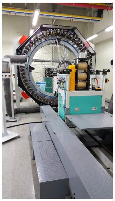 |
| Manufacturer | Tipoel Co. | ||
| Model | TOB-01 | ||
| Braiding width | Adjust the width with the mandrel | ||
| Number of carriers | 128 | ||
| Velocity (rpm) | 50~200 | ||
| Bobbin size (mm) | 55 × 178 | ||
| Dust collector | [TeX:] $$\varphi$$150 mm × 2 hole | ||
| Length (m) | 3.3 | ||
| Breadth (m) | 1.8 |
Table 3.
| Category | 1 | 2 | 3 | 4 | 5 | 6 | 7 | 8 | 9 | 10 |
|---|---|---|---|---|---|---|---|---|---|---|
| Carbon fiber used | T700 | T700 | T700 | T700 | T700 | T800 | T800 | T800 | T800 | T800 |
| Standard | 12K | 12K | 12K | 12K | 12K | 24K | 24K | 24K | 24K | 24K |
| Braiding angle ([TeX:] $$^\circ$$) | [TeX:] $$0^\circ$$ | [TeX:] $$30^\circ$$ | [TeX:] $$45^\circ$$ | [TeX:] $$60^\circ$$ | [TeX:] $$90^\circ$$ | [TeX:] $$0^\circ$$ | [TeX:] $$30^\circ$$ | [TeX:] $$45^\circ$$ | [TeX:] $$60^\circ$$ | [TeX:] $$90^\circ$$ |
| Number of bobbins (ea) | UDP | 128 | 128 | 128 | UDP | UDP | 128 | 128 | 128 | UDP* |
| Mandrel diameter (mm) | UDP | 200 | 200 | 200 | UDP | UDP | 200 | 200 | 200 | UDP* |
| Horn gear (rpm) | UDP | 25 | 27 | 27 | UDP | UDP | 25 | 25 | 27 | UDP* |
| Winding speed (mm/min) | UDP | 350 | 350 | 350 | UDP | UDP | 350 | 350 | 350 | UDP* |
| Feed servo speed (mm/min) | UDP | 200 | 160 | 100 | UDP | UDP | 210 | 170 | 100 | UDP* |
| Braiding quantity (m) | 1 | 5 | 5 | 5 | 1 | 1 | 5 | 5 | 5 | 1 |
*UDP : uni-directional prepreg composite.
블레이딩 직조실험: 섬유 복합재의 구조적 문제 중 하나는 섬유 토우의 비균질적 분포이다. 이는 토우의 크기가 증가함에 따라 더욱 커지는 문제가 생기므로 블레이딩 구조로 인한 복합재의 특성을 고려하여 블레이딩 직조방식을 설계하도록 해야 한다[12−14].
본 연구에서 블레이딩 직조실험은 준비된 탄소섬유의 원사 종류별, 블레이딩 각도별, 작동 조건별로 강체의 물성변화 확인을 위해서, 다음과 같은 단계별 공정조건(Table 4 참조)에 따라서 원사의 준비, 모우발생이 최소화 되도록 하는 분콘 및 권사, 크릴 장착 후 원사의 급사가 최적화 되도록 각 동작부의 조건을 설정하였고, 블레이딩 작업 후에는 직조된 튜브형 원단을 흐트러지지 않게 시험용 컴포지트 시료를 제작하는 후속과정을 진행하였다.
Table 4.
| Process sequence | Process condition | Photos of process output | ||
|---|---|---|---|---|
| 1. Fiber preparation process | T700-12K, T800-24K grade carbon fiber yarn | 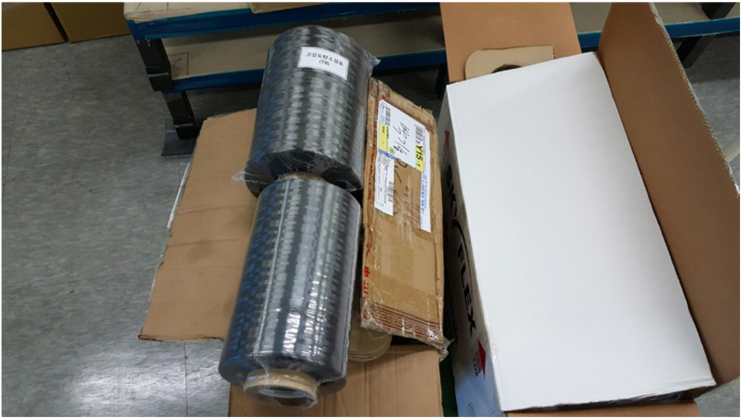 | ||
| 2. Bobbin winding process | 128 bobbin bunkon winding machine | 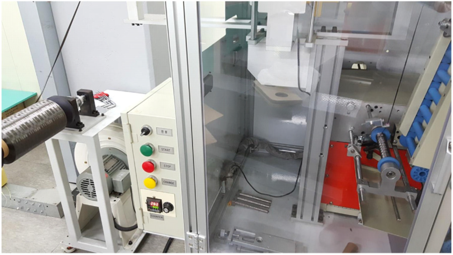 | ||
| Be aware of the risk of carbon fiber wool | ||||
| Set tension conditions that minimize the occurrence of fuzzy | ||||
| 3. Bobbin creel mounting process | Preparation for krill mounting after winding | 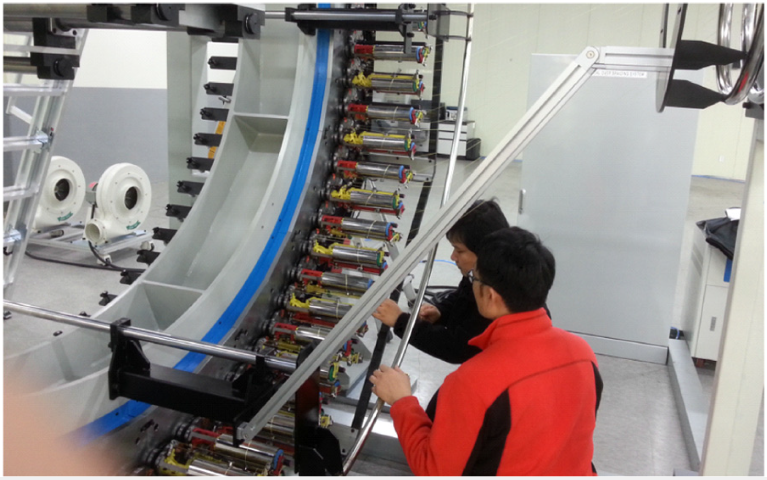 | ||
| Mounting the braider on the mandrel | ||||
| Induce the introduction of the bobbin's mandrel | ||||
| Keep each bobbin tension the same to eliminate sagging or kinking | ||||
| 4. Braiding condition input process | Perform preliminary braiding to set the conditions of each moving part |  | ||
| Check that the weave shape and angle meet the requirements | ||||
| 5. Start of braiding process | After repeated checks, the final operating conditions are confirmed when the operating conditions are completed. | 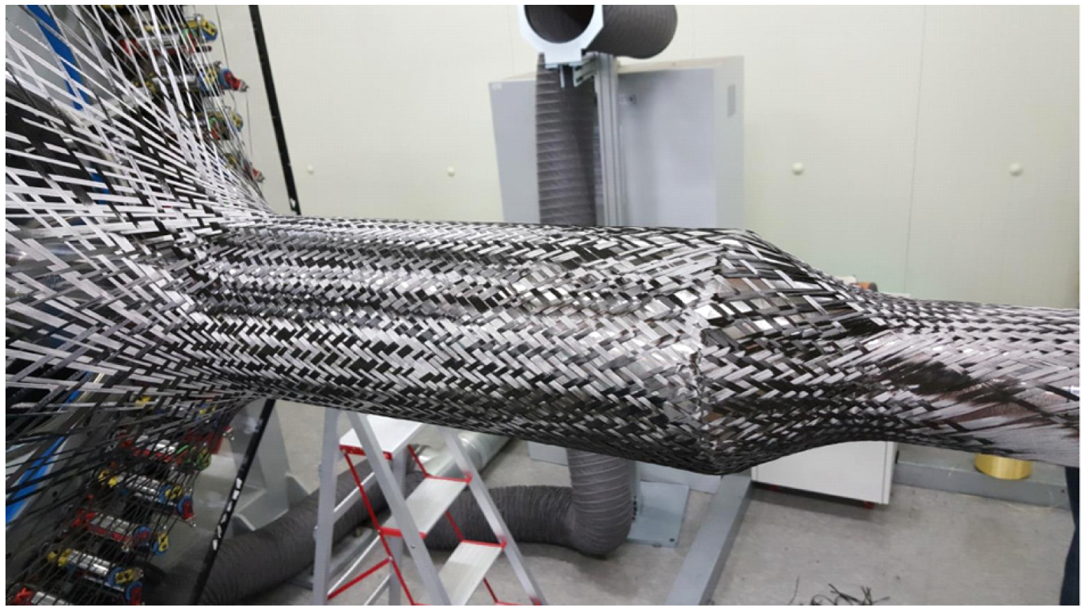 | ||
| Start braiding | ||||
| When braiding is complete, remove the mandrel | 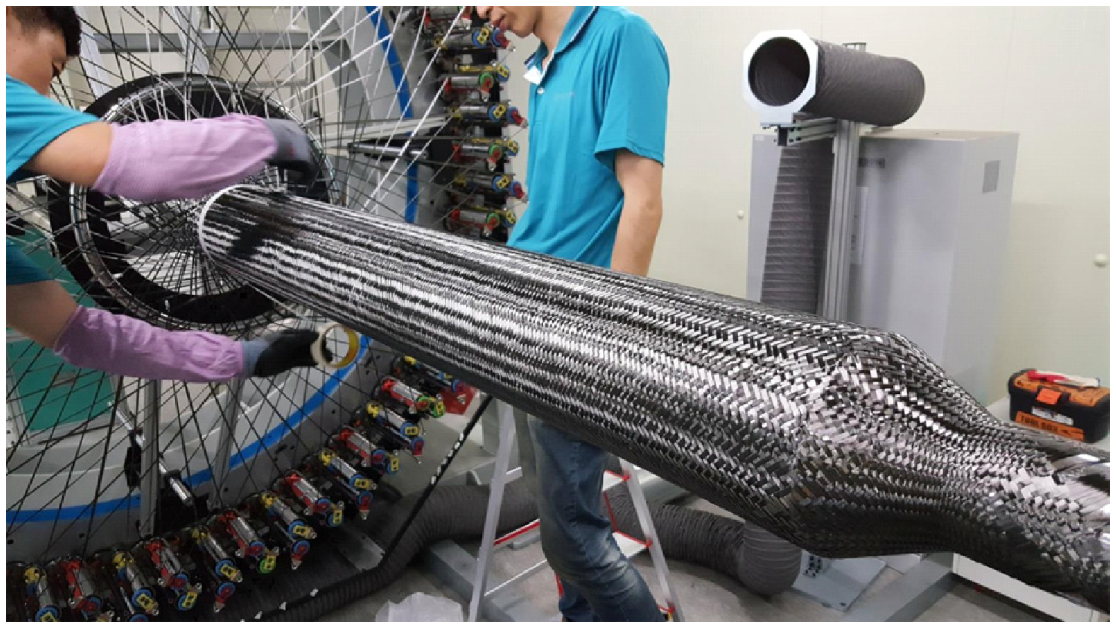 | |||
| End braiding by checking the weave angle | ||||
| 6. End of the braiding process | Condition after the completion of the braiding process |  | ||
| The final result of the braiding prototype | 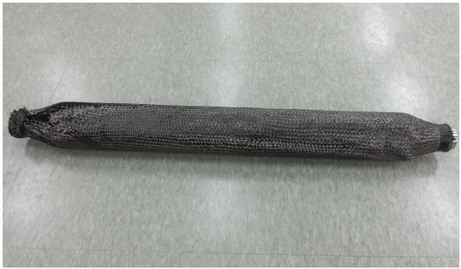 | |||
| 7. Mandrel removal process | Removal of the mandrel from the finished braiding | 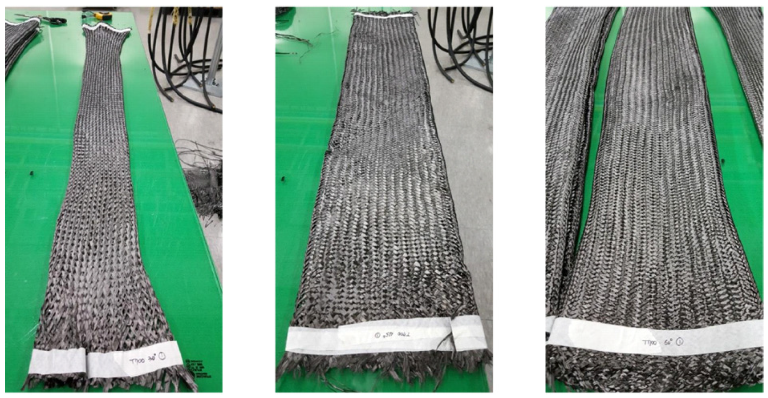 | ||
| Check the weave angle once more | T700 [TeX:] $$30^\circ$$ | T700 [TeX:] $$45^\circ$$ | T700 [TeX:] $$60^\circ$$ | |
| 8. Precautions during the | Normal or not of yarn cutting detection sensor | 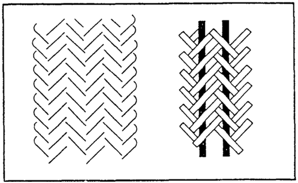 | ||
| Normal yarn force automatic regulator (bobbin inside spring guide attached) | ||||
| Whether the density/thickness of the horn gear can be adjusted | ||||
| 2-axis braiding as shown on the right | ||||
2.3. 탄소섬유 원사 시료 평가
인장강도와 신도 분석: ASTM D4018 시험법(Standard Test Methods for Properties of Continuous Filament Carbon and Graphite Fiber Tows)의 시료준비와 과정의 어려움을 고려하여 이의 대용방식으로 활용되는 준용방식을 사용하였다. 이는 프리프레그(prepreg) 강체의 물성시험에 적용되는 ASTM D3039/D3039M-14 시험용 시편의 시험결과에 탄소 섬유의 체적분율(volume fraction)을 적용시켜 인장특성을 환산하는 방법을 사용하였다.
인장강도시험기(모델: Shimadzu AG-100kNX UTM)을 사용했으며, 시험속도(2 mm/min), 스트레인게이지(Kyowa, [TeX:] $$120 \Omega$$, 표점거리 5 mm)를 사용하였다. Table 5에 실험전∙후의 사진을 나타내었다.
Table 5.
| Before the experiment | After the experiment | |
|---|---|---|
| Sample status |  | 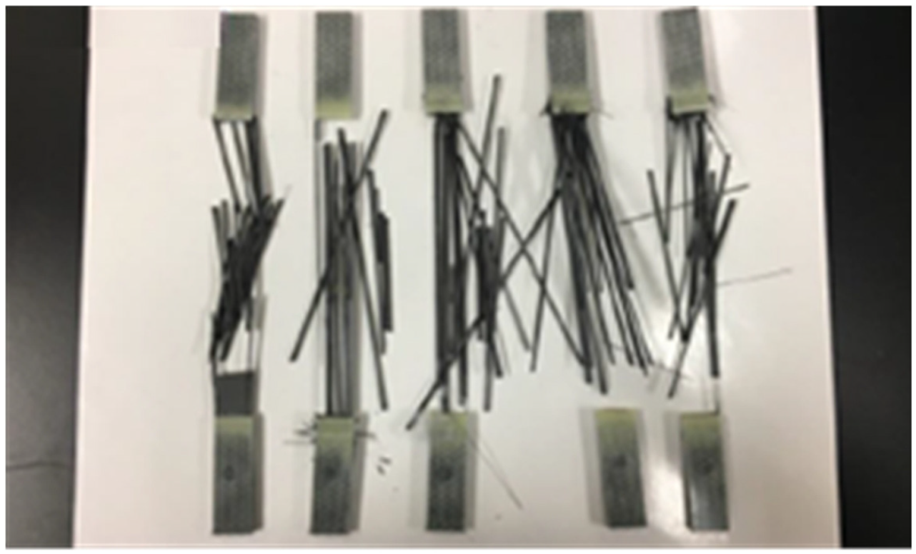 |
탄소섬유 컴포지트 시편 제조 및 평가
탄소섬유 컴포지트 시편 제조
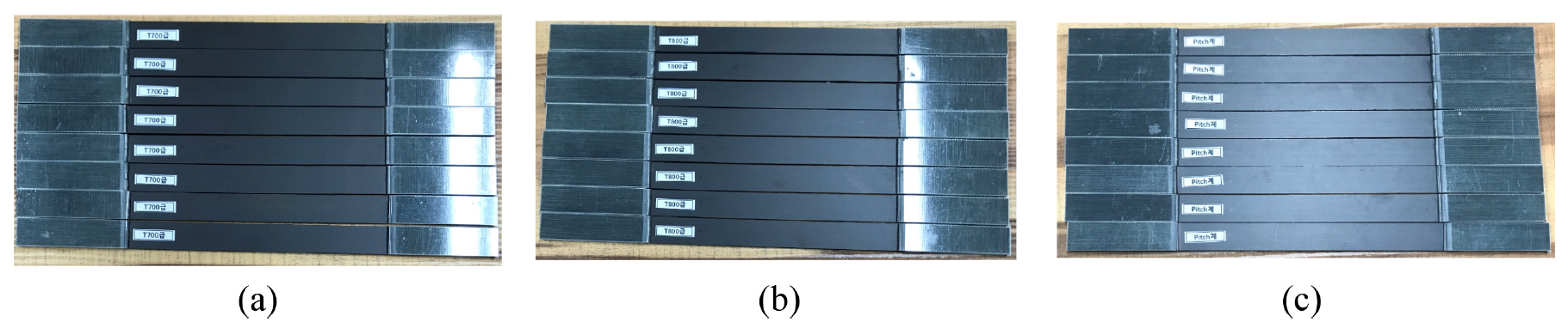
탄소섬유 UD(Uni-Directional) 컴포지트 시편제작: ASTM D3039/D3039M-14 준용시험법을 활용한 원사물성의 확인과 탄소섬유 컴포지트의 블레이딩 직조각도 [TeX:] $$0^\circ$$에서의 물성비교를 위해서는 UD 방향(길이방향으로 [TeX:] $$0^\circ$$)의 시편을 제조하였다. 시편의 제작은 Table 6에 시료 제조공정과 Figure 1에 시료 사진을 나타내었다.
Table 6.
| Process | Process manufacturing condition | Process result |
|---|---|---|
| Laminate manufacturing | Material: SK chemical prepreg | 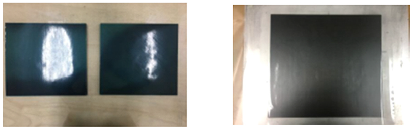 |
| Specification: USN150(T700), UIN150B(T800), URN300B(Pitch) | ||
| Resin: SK standard type (K51) applied | ||
| Sheet molding: SK chemical (vacuum bag molding) |  | |
| Curing conditions: one step curing | ||
| 150oC×30 min, 1~3oC/min temperature increase | ||
| Sample processing | Cutting specimen using diamond saw | 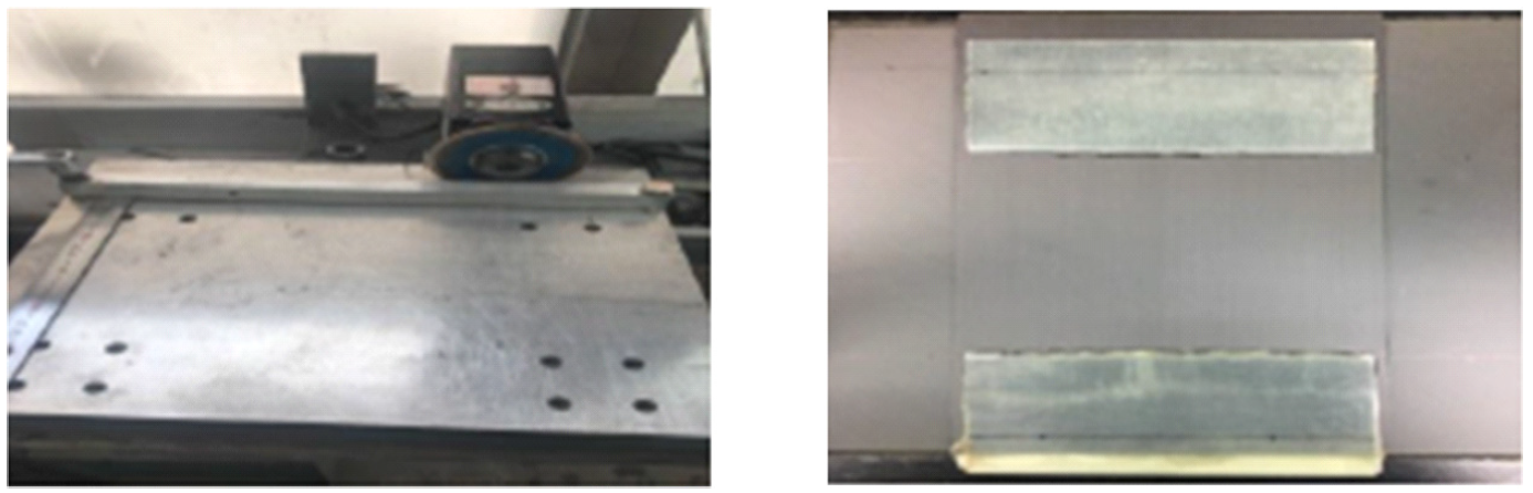 |
| Processing specimen surface manually | ||
| Attaching tab according to specifications |
Figure 1.
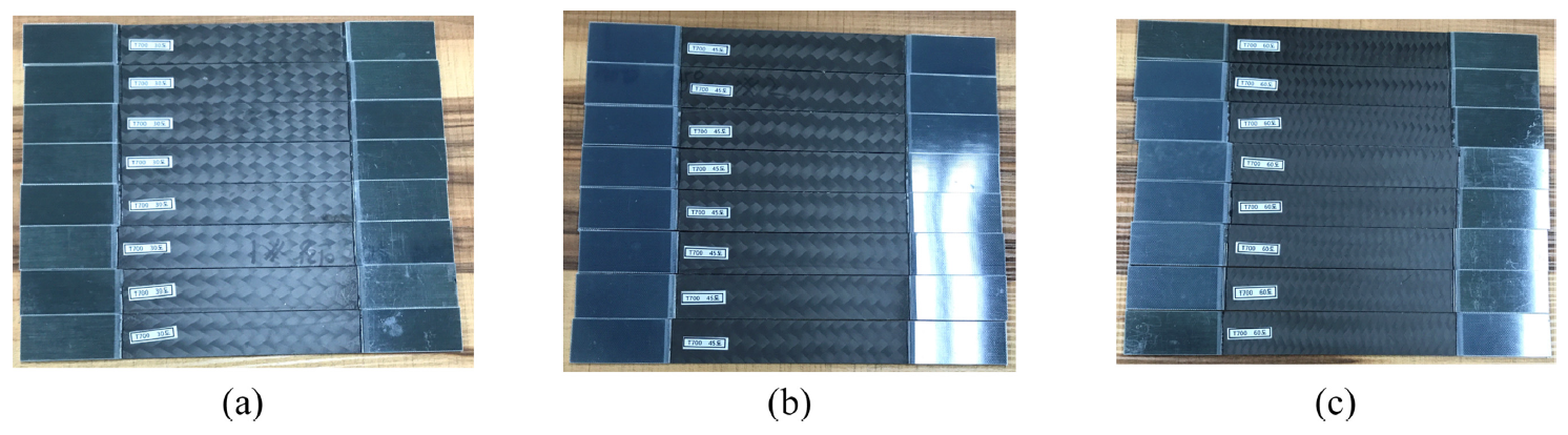
탄소섬유 블레이딩 컴포지트 시료 제조: 블레이딩 방식으로 직조된 탄소섬유 원단에 대해서는 다음의 시편제작 과정을 통해 시험용 강체 시편을 제작하였다. Table 7에 시료 제조공정과 Figure 2에 시료 사진을 나타내었다.
Table 7.
| Process sequence | Process condition | Process result |
|---|---|---|
| Laminate fabrication | Check the braiding weaving condition of the fabric | 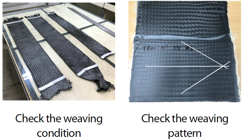 |
| Measure and adjust the braiding pattern | ||
| Cut the composite test standard fabric | ||
| Put in resin (Hand layup) | ||
| Vacuum bag forming at room temperature for 24 hours | ||
| Resin: Kukdo Chemical KFR120 (main agent) plus KFH163 (hardener) |  | |
| Mixing ratio: 100 to 19 | ||
| Composite curing: Room temperature, 24 hours | ||
| Specimen processing | Cut the specimen using a diamond saw | 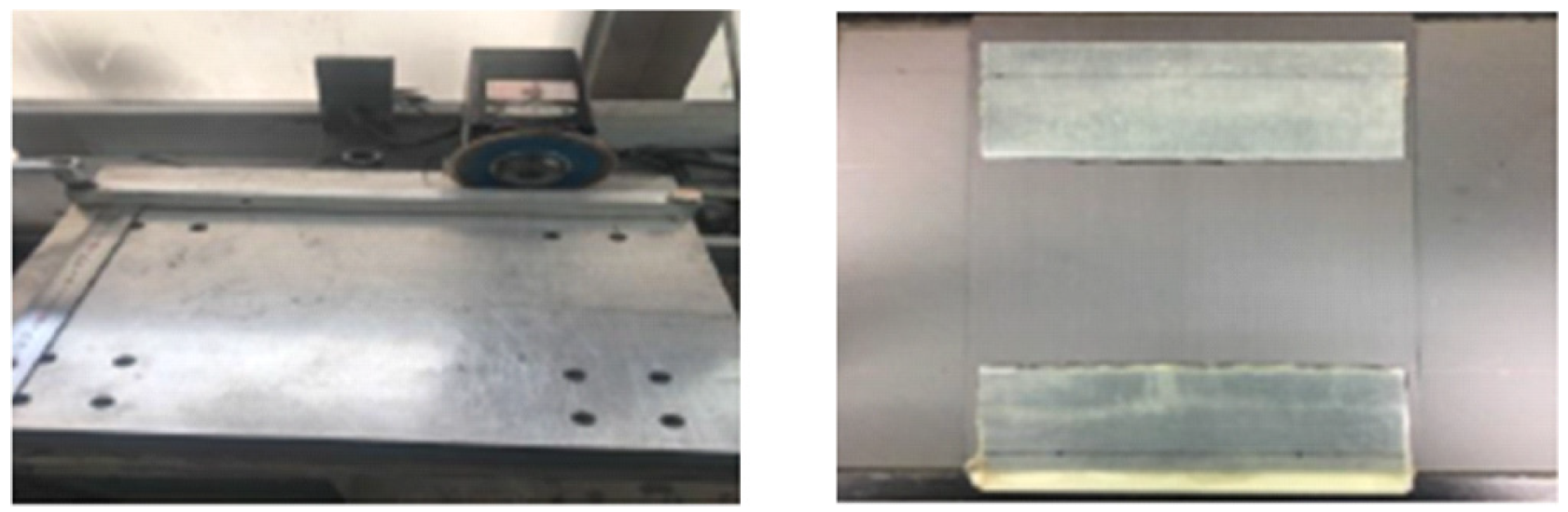 |
| Attach the standard tab after surface processing of the specimen |
Figure 2.
탄소섬유 컴포지트 강체 평가
인장시험: 탄소섬유 컴포지트 인장 강신도 특성을 확인하기 위해 ASTM D 3039/D 3039M 시험법으로써 시험하였다. Table 8에 시험조건을 나타내었다.
Table 8.
| Test equipment | Test grip | Extensometer | Cross head speed |
|---|---|---|---|
| INSTRON 5969 | INSTRON 2716-002, 50 kN Wedge Action grips | Video extensometer (Gage length: 50 mm) | 2 mm/min |
굴곡시험: 탄소섬유 컴포지트의 굴곡 특성 확인을 위해서 ASTM D 790 시험법을 사용하여 시험하였다. 굴곡시험기(model: Shimadzu AG-100kNX UTM)을 사용하였다.
3. 결과 및 고찰
3.1. 탄소섬유 원사의 인장특성
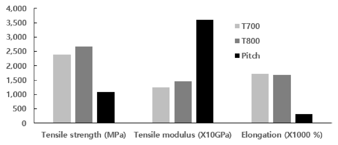
블레이딩용 원사로 선정된 T700과 T800, PITCH계 원사에 대한 인장특성으로 Figure 3과 같은 결과를 얻었다. 탄소섬유 종류별 인장특성은 강도에서는 T800가 가장 우수하고, 신도에서는 Pitch계 원사가 가장 탄성이 큼을 확인할 수 있다. 원사별로 가지고 있는 상대적인 특징을 그대로 보유하고 있음을 확인할 수 있다.
3.2. 블레이딩 강체의 인장특성
직조각도에 따른 인장변형 특성: 상기의 블레이딩용 원사로 선정된 탄소섬유을 사용하여 앞서의 블레이딩 조건 하에서 강체 시편을 제작하여 그 물성을 확인하여 본 결과, 강체의 물성은 원사의 물성에 직접 연결되어 비례하여 나타나고 있음을 알 수 있다. Figure 4에 원사종류에 따른 인장변형 그래프를 나타내었다.
Figure 4.
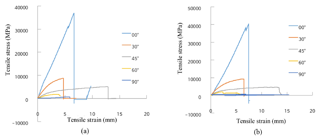
[TeX:] $$0^\circ$$(UD 방향)에서는 순수한 탄소섬유 강체의 변형특성을 보이다가 직조각도를 증가시키면 강체의 특성보다는 고분자 수지에서의 인장변형 특성으로 변화되는 것을 확인할 수 있다.
원사종류에 따른 인장변형 특성: 탄소섬유 컴포지트(composite) 강체의 인장특성은 원사종류별 특징이 그대로 유지되고 있으며, UD 방향([TeX:] $$0^\circ$$)으로부터 원사의 축 방향으로부터의 직조각도가 증가할수록 강도 및 탄성이 급격히 낮아지게 된다. 블레이딩 직조시 원사의 교차각도를 다르게 한 강체의 원사종류별 변형특성을 관찰하면, 원사종류에 관계없이, [TeX:] $$0^\circ$$(UD 방향)에서는 순수한 탄소섬유 강체의 변형특성을 보이며 직조각도를 증가시키면 일반적인 섬유 고분자 물질에서의 인장변형의 특성을 보이게 됨을 확인할 수 있다. Figure 5에 관련 결과를 나타내었다.
Figure 5.
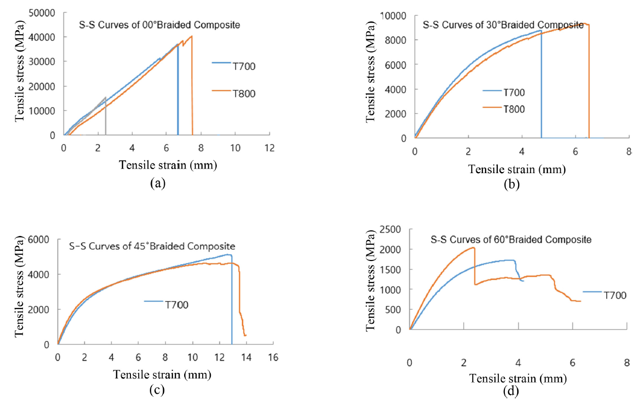
실제로, 탄소섬유 T700 원사와 T800 원사로 조성한 블레이딩 강체에서의 직조각도별 강신도 변화를 비교해 보면, 직조각도가 증가할수록 T700 원사와 T800 원사의 물성차이가 강체에서는 상대적으로 줄어들 가능성이 있음을 보여주기도 한다. 이는 직조각도가 증가함에 따라 강체의 경화에 사용되는 고분자수지의 영향이 원사의 영향력보다 더 증가할 수 있음을 의미한다고 할 수 있다.
3.3. 블레이딩 강체의 굴곡특성
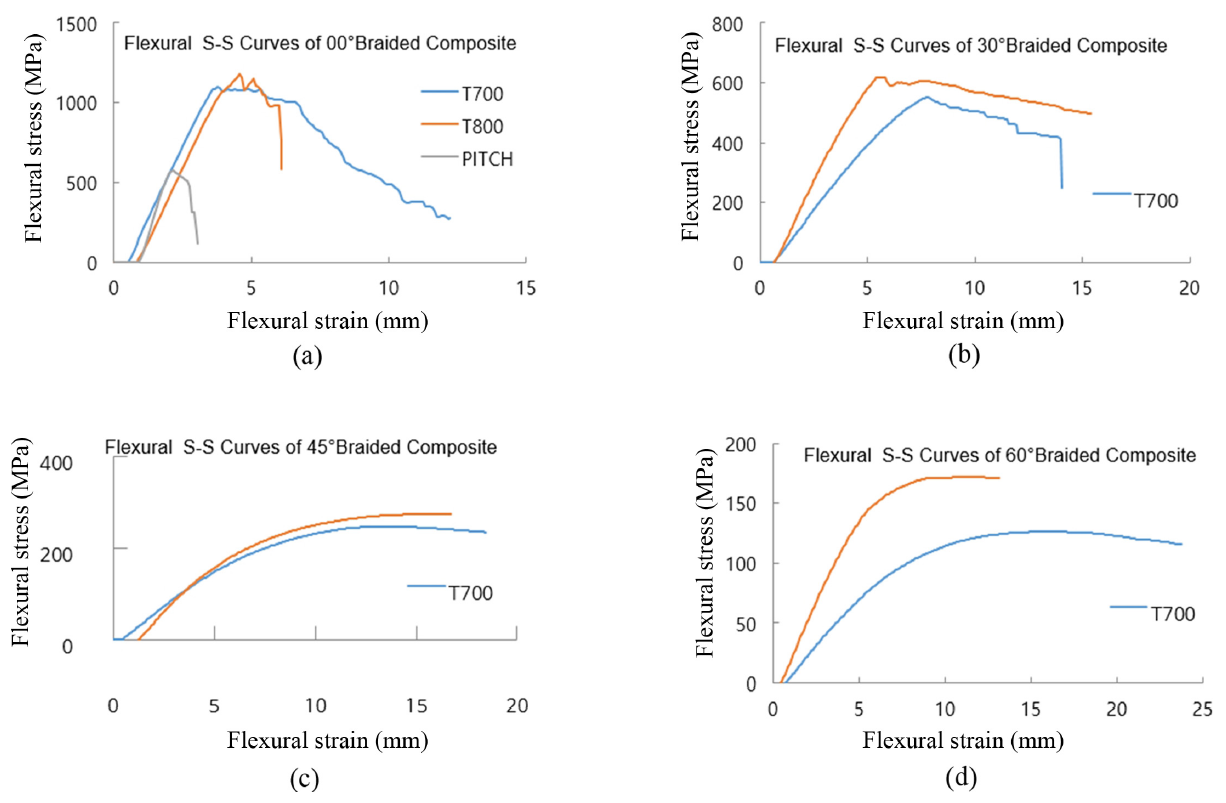
직조각도에 따른 굴곡변형 특성: 블레이딩 직조각도를 변경하여 직조된 강체의 굴곡변형 특성을 확인해 보면, 인장 변형에서와 동일하게 급격한 굴곡강도의 저하와 신율의 증가를 보이게 된다. 이러한 경향은 T700 원사에서보다 상대적으로 고강도 특성인 T800 원사에서 강도저하가 급격해짐을 볼 수 있다. Figure 6에 관련 결과를 나타내었다.
Figure 6.
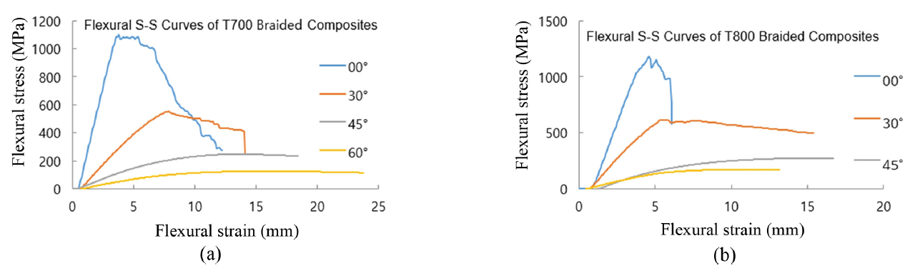
이러한 현상의 주된 이유로서는 굴곡특성에서도 블레이딩 직조시에 섬유간 교차영역에서 발생된 공간으로 인해 탄소섬유 체적분율이 UD형 프리프레그의 교차적층시보다 작아진 것이 주원인일 것으로 추정된다. 따라서, 블레이딩 강체의 굴곡특성 설계에서도 직조각도 뿐만 아니라 직조시의 탄소섬유 체적분율을 중요한 요인으로 고려해야 할 것으로 관찰된다.
원사종류에 따른 굴곡변형 특성: 원사 종류에 따른 블레이딩 직조시 교차각도를 다르게 한 강체의 굴곡변형 특성을 확인해 보면, [TeX:] $$0^\circ$$(UD 방향)에서는 탄소섬유 강체의 변형특성인 직선형 변형형태를 보이다가 직조 교차각도가 증가하면 점차 곡선형 변형형태를 보임을 알 수 있다. Figure 7에 관련 결과를 나타내었다.
Figure 7.
이는 인장변형에서와 동일하게 직조각도를 증가시키면 순수한 탄소섬유 강체특성으로부터 플라스틱 물질의 변형 특성으로 전환되며, 강체의 경화에 사용되는 고분자수지의 영향이 원사의 영향력보다 더 증가하게 된다는 것을 의미한다고 할 수 있다.
4. 결 론
본 연구는 탄소섬유 종류에 따른 블레이딩 직조 방식과 그에 따른 강체의 인장 및 굴곡 특성을 조사하였다. T700, T800, PITCH계 원사를 대상으로 다양한 직조 각도에서 강체의 물성을 확인한 결과, 몇 가지 중요한 결론에 도달하게 되었다.
첫째로, 탄소섬유 원사의 종류가 강체의 인장 특성에 직접적인 영향을 미친다는 점이 밝혀졌다. T800 원사는 높은 강도를, PITCH계 원사는 높은 신도를 갖고 있어 각각의 원사가 가진 상대적 특징을 유지하고 있다는 점을 확인하였다. 원사의 인장 특성은 직조 직후의 강체 특성과 밀접히 연관되어 있었다.
둘째로, 블레이딩 강체의 물성은 원사의 물성과 직조 각도에 따라 달라진다는 점을 알 수 있었다. 0도(UD 방향)에서는 순수한 탄소섬유 강체의 특성을 보였다가, 직조 각도가 증가할수록 고분자 수지의 특성으로 변화되는 현상이 관찰되었다. 이는 직조 각도에 따라 강체의 물성 변화를 예측하고 제어할 수 있는 중요한 정보였다.
셋째로, 직조 각도가 증가함에 따라 인장 및 굴곡 강도가 급격하게 낮아지는 것을 확인하였다. 이는 특히 고강도의 T800 원사에서 두드러지게 나타났으며, 이는 블레이딩 강체의 설계 시 직조각도와 탄소섬유의 체적 분율을 신중하게 고려해야 한다는 점을 시사한다.
마지막으로, 블레이딩 방식의 탄소섬유 강체는 기존의 프리프레그 방식과는 다른 물성을 지니고 있으며, 공정 단순화와 비용 절감, 성능 향상의 가능성을 보여주었다. 이는 국내외 연구 및 산업 분야에서 블레이딩 직조 방식을 활용한 탄소섬유 강체의 응용이 더욱 활발히 진행될 수 있는 기반이 되었다.
본 연구를 통해 얻은 결과는 블레이딩 방식의 탄소섬유 강체 제조에서 올바른 공정 조건을 설정하는 데 중요한 기초자료가 될 것이다. 향후 연구에서는 다양한 탄소섬유 토우와 고분자 수지 조합을 실험하여 더욱 정교한 공정 조건을 도출하고, 블레이딩 방식의 탄소섬유 강체의 추가적인 응용 가능성을 고찰 할 필요가 있다.
감사의 글
이 논문은 부천대학교 교내학술연구비의 지원을 받아 얻은 결과임을 보고 드립니다.
References
- 1 J. W. Park, S. S. Cheon, and J. U. Cho, " A Study on Fracture Behavior of Center Crack at Unidirectional CFRP due to Stacking Angle" , Composites Research, 2016, 29, 342−3469.custom:[[[-]]]
- 2 T. Y. Kim, H. S. Kim, and H. G. Shin, "Investigation Into the Drilling Characteristics of Carbon Fiber Reinforced Plastic (CFRP) with Variation of the Stacking Sequence Angle", Journal of KSMTE, 2014, 23, 250−258.custom:[[[-]]]
- 3 M. K. Seo, K. E. Choi, B. G. Min, and S. J. Park, "Carbon Fibers (I): General Understanding and Manufacturing Techniques of Carbon Fibers" , Carbon Letters, 2008, 9, 218−231.custom:[[[-]]]
- 4 J. S. Kim, H. J. Yoon, H. S. Lee, and T. S. Kwon, " A Study on Failure Mechanisms 01 Composite Tubes with Woven Fabric Carbon, Glass and Kevlar/epoxy Under Compressive Loadings" , Journal of the Korean Society for Railway, 2009, 12, 590−596.custom:[[[-]]]
- 5 T. N. Geleta and K. S. Woo, "Prediction of Material Properties for Tri-axial Braided Textile Composites", KSAS Spring Conference, 2016, pp.109−110.custom:[[[-]]]
- 6 Y . U. Jeon, Y . H. Kim, P . H. Kim, H. Y . Kim, and J. S. Park, " A Prediction of Braiding Composite Strength Using Approximate Method" , KSAS Spring Conference, 2017, pp.75−76.custom:[[[-]]]
- 7 W . Ki, J. S. Kang, H. K. Shin, and S. J. Kang, "Manufacturing and Analysis of CFRP Component for Automobile using Braiding Process" , KSMTE Spring Conference, 2014, p.80.custom:[[[-]]]
- 8 H. S. Park, J. H. Choi, J. M. Koo, and C. S. Seok, "Fatigue Damage Evaluation of Woven Carbon-Fiber-Reinforced Composite Materials by Using Fatigue Damage Model", Journal of KSME-A, 2010, 34, 757−762.custom:[[[-]]]
- 9 T. J. Kang, S. G. Jung, and J. R. Yun, "Multi-axial Textile Structure Textile Composites Optimal Design Net-shape Manufacturing Technology Circular Braiding Resin Transfer Molding, " KSEF , 2002, p.10.custom:[[[-]]]
- 10 S. E. Kim, Trends and Technology Development Directions of Carbon Fiber Reinforced Composites (CFRP) Industry, PD ISSUE REPORT, 2015, Vol. 15, pp.101−121.custom:[[[-]]]
- 11 ASTM D4018, "Standard Test Methods for Properties of Continuous Filament Carbon and Graphite Fiber Tows" , 2023.custom:[[[-]]]
- 12 ASTM D3039, "Standard Test Method for Tensile Properties of Polymer Matrix Composite Materials" , 1971.custom:[[[-]]]
- 13 ASTM D790, "Standard Test Methods for Flexural Properties of Unreinforced and Reinforced Plastics and Electrical Insulating Materials" , 1970.custom:[[[-]]]
- 14 https://www.uster.com/, (Accessed January 4, 2025).custom:[[[https://www.uster.com/,(AccessedJanuary4,2025)]]]